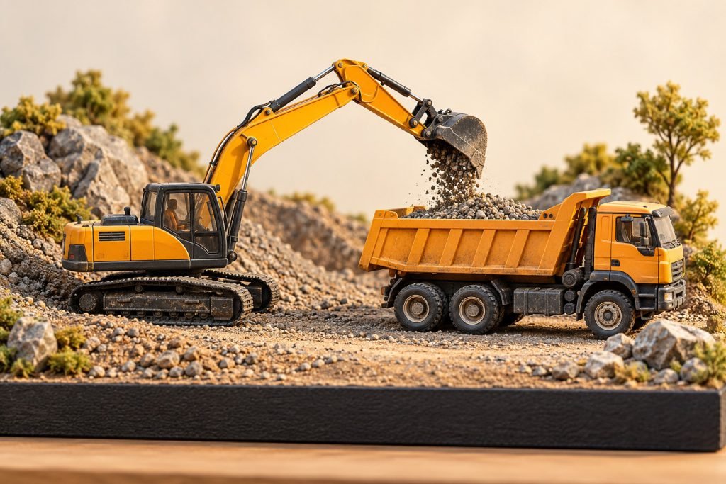
Position the bucket, truck bed and counterweight before fixing scenery to a base. Matching scale is necessary for a consistent scene, but it does not prove that a particular miniature excavator can reach a particular miniature truck.
Choose one moment in the loading cycle
Decide whether the bucket is approaching the bed, positioned above it or moving away. Draw the intended viewing direction and keep the decisive gap visible. A parked pair needs less functional compatibility than a frozen loading moment, so do not buy an expensive attachment solely for a pose you will not use.
Measure the actual models in the chosen pose
Record truck-bed height and inside opening, bucket width, reachable bucket height and horizontal clearance. Include the excavator’s counterweight sweep and the truck cab. Model joints may stop short of real-machine positions; use the actual miniature or a reliable exact-pose measurement, not a scaled full-size brochure.
Mock up the scene before adding terrain
Put paper rectangles on the intended base and mark the machine centers. Add a side-view sketch for the bucket-to-bed relationship. If you own the models, set them down without loose aggregate and check the view from the intended display height. Do not load the bucket or bed to test strength. A photo-friendly pose can be represented without loose material.
Resolve the limiting dimension
If the bucket cannot clear the side, change the scene, machine position or model choice. Do not force the arm, remove a truck side or assume a raised scenic platform is automatically stable. The 745 truck and 395 ME excavator are individual display candidates, not a verified compatible pair. Finish with an observed clearance and a stable arrangement.
Exact-model reference: 85528 sample inspection, 85959 sample inspection. These examples do not establish behavior for every model.